AVB Overview
The Soundweb London BLU-805 and BLU-325 are capable of sending and receiving Ethernet AVB audio. AVB, or Audio/Video Bridging, is a common name for a set of IEEE standards that ensure the transmission of high quality streaming audio and video over a standard Ethernet connection.
Note: Soundweb London devices cannot send, receive, or process video data.
As a networked audio transport, AVB is similar to CobraNet in many ways, with a few key differences:
Non-proprietary, based on open standards
Guaranteed delivery of media
No need to specify “multicast” or “unicast” transmissions. Any transmitted AVB stream can have 1 or more receivers. Unlike CobraNet multicast bundles, AVB streams with multiple receivers will only transmit to those receivers, and they will not needlessly broadcast across the entire network
Simplified network switch management due to the above three bullets
Reduced latency
Latency range for CobraNet in Soundweb London: 1.33ms – 5.33ms
Latency range for AVB in Soundweb London: 0.5ms – 2.0ms
Increased audio I/O capability per device
Max CobraNet audio channels in Soundweb London: 32x32 per device
Max AVB audio channels in Soundweb London: 64x64 per device
The AVB standards were created through a consortium of industry experts which was then ratified and accepted by the IEEE industry standards body. This means that AVB is not just another proprietary non-standard protocol that floats on top of the Ethernet layers. AVB is the Ethernet. The big difference between AVB and previous solutions for network streamed media (such as CobraNet) is that the IEEE controls the Ethernet standards, which allowed for the specifications of not just the endpoints, but more importantly the switches. This allows an entire network to be designed to accommodate audio and video, with compatibility between AVB devices that are made by different manufacturers.
The standards specify a means to provide time synchronized low latency audio and video over standard CAT5e cable. The majority of the bandwidth across the network is reserved to carry audio and video, and to guarantee the arrival of a signal
.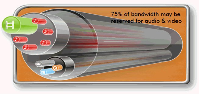
In order to accomplish transporting the large amount of information required by both audio and video across a network, bandwidth is reserved and defended throughout the network by the switches. By default the switch will reserve and defend 75% of network bandwidth to be exclusively used for AVB media, both audio and video. This will guarantee precisely synchronized audio/video without interruption from non-time sensitive data and communication, such as email or control protocol traffic (also known as “Best Effort” traffic). By design, the switch will not allow for the audio or video to become corrupted.
Each audio/video sample is time-stamped with exactly what time to play, and all AVB devices are synchronized to a common clock known as the Grand Master clock. This allows for the synchronization of multiple streams of audio and video to be rendered at the correct time with respect to each other.
An AVB network inherently supports multiple simultaneous sample rates and (sample) clock sources which allow video and audio streams to be synchronized even though they travel on different paths with different sample rates.
Details for the six IEEE audio/video bridging standards (802.1AS, 8021.Qat, 802.1Qav, 802.1BA, 1722, and 1733) are available at IEEE.org and AVnu.org
Soundweb London AVB Module
The BLU-805 and BLU-325 devices are fitted with an AVB module. The module offers a Primary and a Secondary AVB port. Under normal operation, only the Primary port transmits and receives data to and from the network. Should the Primary port or connection fail, the AVB module automatically switches to receive from and transmit with the Secondary port. This must be considered in the network design. It may be appropriate to connect the Primary AVB port to a Primary network and the Secondary AVB port to a Secondary, backup network. In this event, it should be noted that the backup network should in some way be bridged to the Primary network in order for the audio data to be present on the Secondary network should the module switch over.
NOTE: The secondary port is not currently enabled. It will be enabled in a future release of HiQnet London Architect.
Network Connections
Devices can only be connected together through switches which support AVB. Examples of such switches are the BSS Audio / NETGEAR GS724T Ethernet Switch or the LABX Titanium 411 Ruggedized AVB Ethernet Bridge Switch. Do not connect the AVB ports to any switch which does not support AVB.
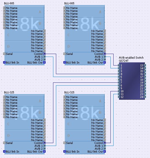
The AVB devices can be wired in London Architect as shown.
Note
that the standard Ethernet ports (labeled “Control” in London
Architect) must also be physically connected to ensure communication
between the devices. In the same way that Soundweb London CobraNet
ports send and receive audio only (not control data), the Soundweb
London AVB ports send and receive audio only.
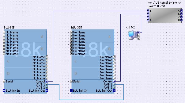
In 2-device systems, it is possible to connect the AVB ports directly together, as shown
.
Cable Requirements
CAT5e or better cable may be used, allowing cable runs of up to 100m per connection. If more distance is required, Gigabit fiber converters—such as the BLU-MC1—can be used. 100Mb (“Fast Ethernet”) fiber converters cannot be used for the Soundweb London AVB ports, because they are Gigabit ports.
AVB Audio Channels per Device
Audio channel rules
The Soundweb London AVB module can transmit 64 channels and receive 64 channels simultaneously (64x64).
The card cannot transmit more than 64 channels or receive more than 64 channels in total.
Stream rules:
An AVB stream may contain between 1 and 32 channels (inclusive).
Each AVB card can transmit up to 64 streams
Each AVB card can receive up to 62 streams with a further 2 streams reserved for MCN
Talker (Transmit)
Example A: 2 streams of 32 channels
Example B: 32 streams of 2 channels
Example C: 29 streams of 2 channels, plus 1 stream of 5 channels plus 1 stream of 1 channel
Example D: 61 streams of 1 channel plus 1 stream of 3 channels
Example E: 64 streams of 1 channel
Listener (Receive)
Example A: 2 streams of 32 channels
Example B: 32 streams of 2 channels
Example C: 29 streams of 2 channels, plus 1 stream of 5 channels plus 1 stream of 1 channel
Example D: 61 streams of 1 channel plus 1 stream of 3 channels
Example E: 62 streams of 1 channel
There are thousands of permutations as long as the total number of channels transmitted is 64 or less. Similarly, the total number of channels received must be 64 or less.
Note: It is advised to configure and use (multi-channel streams) vs. (single channel streams). This is the most efficient transport method for transmitting and/or receiving AVB audio channels across a network switch.
Resource Meter
The configuration view of a BLU-805 or BLU-325 contains a second resource meter which displays the AVB resources only. This AVB resource meter shows the % of streams and channels used for a particular configuration as shown below.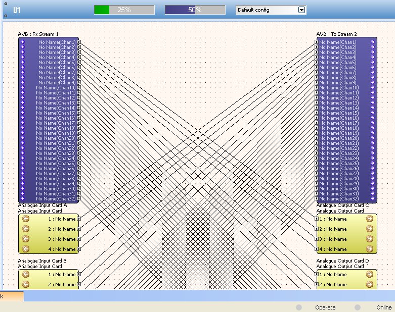
In the above example, 32 AVB input channels are enabled, and 32 AVB output channels are enabled. 32x32 is exactly half of the BLU device’s AVB I/O capability. Therefore 50% is displayed in the AVB resource meter (which is the same shade of purple as the AVB input/output objects).
In a design where, for example, 32 AVB input channels are enabled, 50% will still be displayed even though no output channels have been enabled. As output channels are enabled the resource meter will continue to display 50% until the number of outputs channels enabled exceeds 32.
In a design where, for example, 33 AVB input channels are enabled and no AVB output channels are enabled then 51% will be displayed on the resource meter. Again as output channels are enabled the resource meter will continue to display 50% until the number of outputs channels enabled exceeds 32.
The above examples also apply to the resource meter where it is the output channels which have been assigned.
Creating Streams
In the configuration window of a BLU-805 and a BLU-325, by default there is one AVB Input processing object (Rx, Listener) and one AVB Output processing object (Tx, Talker). Initially they have no nodes on them.
You can add or remove as many AVB processing objects as you wish inside a BLU-805 and BLU-325 although the number of streams is limited as described.
Streams are defined system-wide. They can be created using the dialog which can be accessed in several ways:
The System Menu - ‘System->AVB Streams...’
When creating a new AVB Input or Output object - the dialog pops up when the object is created
By opening the dialog from the AVB input or output properties by clicking on an AVB Input or Output object, then accessing the Stream ID parameter from the properties.
Use the above dialog to view details of, add, delete and edit streams.
Define AVB Stream
Click on the 'NEW' button to open the 'Define AVB Stream' dialog shown below.
Name - The name of the stream. This is used within London Architect only.
ID Type - Full or Harman. A stream is given a system wide unique ID. There are 2 types of ID :-
Full - The full 8 byte AVB stream ID. This is usually displayed in hexadecimal and is used to connect up to non-Harman AVB equipment.
Harman - A simpler, smaller stream ID which is used instead of the full stream ID within a Soundweb London system. This number is simply shorthand for a range of full 8-byte IDs reserved by Harman.
ID - If the ID Type is ‘Full’ then the ID is a 16 digit Hexadecimal number. E.g.000FD4001E710000. If you are interfacing to non-London AVB equipment you should find the stream ID from the 3rd party user interface or software interface.
Description - A longer description of the stream for documenting the design. This is used within London Architect only.
Number of Channels - The number of channels in the stream. Changing this number will add/remove channels from the stream
Channel List :- The list of channels within a stream. Channels can be added, deleted, moved using the buttons on the right. To edit the name of the stream click on the channel name.
Channel names are displayed on the Stream Tx and Rx objects after the signal name.
Stream Restrictions
Streams are subject to the following restrictions :-
An AVB card cannot receive a stream that it is transmitting. (See example A)
An AVB card cannot receive the same stream more than once. (See example B)
An AVB stream ID must be unique within an AVB network. (See example C)
If London Architect detects a problem with a stream the AVB Input and AVB Output objects are drawn in red. In this state a tooltip will show what the error is:-
Example A:

Example B:
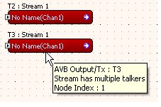
Example C:
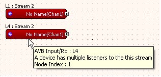
Control Panel
PTP (Precision Time Protocol)
PTP Grand master - This indicator will be amber when the device has arbitrated as the PTP clock grand master for the cloud.
PTP Locked - This indicator will be green when the device is grand master for the cloud or if the device has synchronized with the grand master clock.
PTP Grand Master ID - This is the ID of the PTP clock that has arbitrated as grand master for the cloud.
PTP Priority 1 - This value controls the most significant value of the BMCA (Best Master Clock Arbitration) priority vector that is used in arbitration of the clock grand master. Set the priority of the PTP Grand Master here. The device with the highest priority will be Grand Master. A priority setting of 0 is the highest priority and a setting of 255 has the lowest priority.
PTP Priority 2 - This value controls the least significant value of the BMCA priority vector.
AVB Peer Primary - This indicator will be green when the device has recognized that it (the primary port) is a member of the AVB cloud.
AVB Peer Secondary - This indicator will be green when the device has recognized that it (the Secondary port) is a member of the AVB cloud.
Media Clock
Media Clock Master - This indicator is amber when the device is the Media Clock Master for this media clock domain.
Media Clock ID - This identifier is used by London Architect to ensure that signals routed from one device to another are synchronized to the same media clock.
Media Clock Locked - This indicator is green when the device is listening to the house clock stream for this domain and the house clock has been successfully recovered from it.
Media Clock Priority - This value is compared during Media Clock Master Arbitration to determine which device should be the Media Clock Master. A lower value corresponds to higher priority clock, so setting this SV to 0 would make the device win most often and 255 would make the device win least often.
MCN Pilot Stream ID - The full stream ID of the current pilot stream.
The following parameters can be accessed from the Design Tree
MCN Primary MAC - Shows the MAC address of the current MCN clock master.
MCN Reserve MAC - Shows the MAC address of the reserve MCN clock master.
PTP Path Delay Primary - Delay (in nanoseconds) between this device and its immediate peer on the network.
PTP Path Delay Secondary - Delay (in nanoseconds) between this device and its immediate peer on the network.
VLAN ID - The ID of the VLAN used by the AVB traffic.
Primary Port MAC - The MAC address of the primary Ethernet port of the AVBX card.
Secondary Port MAC - The MAC address of the secondary Ethernet port of the AVBX card.
Transmitter Object (Talker) Properties
Stream ID - The ID of the stream. Either a full 8 byte stream ID or a shorter Harman ID.
State (Stream Active) - True when the stream is being transmitted to at least one listener.
Presentation Offset - The latency setting of the talker (in nanoseconds). The default setting is 2ms (2,000,000ns). When set to 2ms, the stream is guaranteed to be delivered to the receiving device exactly 2ms after transmission, but only if there are 7 or less network switch hops in between the transmitter and receiver. This setting can be reduced, at the expense of fewer allowed switch hops.
Receiver Object (Listener) Properties
Stream ID - The ID of the stream. Either a full 8 byte stream ID or a shorter Harman ID.
State (Stream Active) - True when the stream is being received.
Force Pilot Stream - When 'on' the RX stream is used as the AVB pilot stream. The pilot stream is the stream that the London BLU device recovers the audio clock from. Therefore, if you are interfacing to a 3rd party device which does not support MCN, you will need to set the BLU-805 or BLU-325 to sync its audio clock to the stream coming from that device. So, to receive an audio stream from an AVB console, you use the full stream ID and set force pilot stream to On.
Clocking
The device will clock from the AVB under any of the following conditions
It is an MCN slave and it is locked to an MCN pilot stream.
It is an MCN master and another device is receiving its MCN pilot stream.
It is clocking off one of the RX streams using the ‘Force Pilot Stream’ option.
See BLU link Mastership for further clocking scenarios where the device is not clocking from the AVB..
AVB vs CobraNet I/O Comparison
Users already familiar with CobraNet will perhaps find it useful to compare the two transports’ I/O capabilities.
Whereas CobraNet-capable BLU devices can simultaneously send and receive up to 32 channels of CobraNet audio (32x32), AVB-capable BLU devices can simultaneously send and receive up to 64 channels of AVB audio (64x64).
Whereas up to 8 channels of audio can be packaged into 1 CobraNet “bundle,” up to 32 channels of audio can be packaged into 1 AVB “stream.”
Whereas CobraNet-capable Soundweb London devices can simultaneously transmit up to 4 CobraNet bundles and receive up to 4 CobraNet bundles (4x4), AVB-capable Soundweb London devices can simultaneously transmit up to 64 streams and receive up to 62 streams (62x64).
PTP (Precision Time Protocol)
Precision Time Protocol is used to synchronise time in the AVB cloud. One device is elected as Grand Master and each device uses PTP to calculate the exact time. Once the devices have agreed on the current time they can then create synchronised audio clocks using Media Clock Negotiation.
MCN (Media Clock Negotiation)
Media Clock Negotiation is used to synchronise audio clocks between devices in a single audio clock domain. AVB allows multiple media clocks on the network with multiple sample rates co-existing. Each talker stream must specify which media clock it is using. There can be 256 different media clocks on an AVB network.
Individual AVB devices will have a number of audio clocks that it uses. Typically, there is one audio clock used by a device and all the audio within the device uses that clock.
Media clocks are propagated throughout the AVB network using streams. These streams may also contain data (audio), but that is not a requirement. For each media clock domain, primary and secondary clock masters are negotiated using the MCN protocol. If the MCM priorities for all devices in a given PTP cloud are the same, the device with the lowest MAC address wins. The primary and secondary clock masters create media clock streams which all devices can listen to. Devices monitor the primary and secondary media clock streams, and if the primary fails the secondary will be promoted to primary and a new secondary media clock master will be negotiated based on the defined priority or lowest MAC address.
Suitable Switches
- BSS Audio / NETGEAR GS724T Ethernet Switch
- LABX Titanium 411 Ruggedized AVB Ethernet Bridge Switch