BLU link
Overview
BLU link is an audio bus found on all BLU-800/BLU-805, BLU-160, BLU-320/BLU-325 and BLU-120, BLU-100, BLU-101 and BLU-102 devices. It carries 256 channels of audio at 48kHz, and 128 channels at 96kHz, both at 24bit (note that BLU-100, BLU-101 and BLU-102 are restricted to 48 channels at 48kHz). When connected in a loop, it has redundancy, allowing any one BLU link cable to break while still maintaining audio.
Hardware Configuration
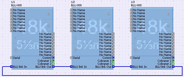
On the rear of the BLU link devices there are two BLU link ports. One is the BLU link In, and the other BLU link Out. Devices are connected together by wiring out to in on all of the devices within your BLU link network, making sure that the loop is complete so that there are no empty BLU link ports. This is how three BLU-800 devices should be wired together:
You should not connect the BLU link ports to anything else
other than BLU link ports. BLU link will not function
if you tried to connect the BLU link to an Ethernet switch
for example.
Fault Tolerance
The network is capable of a degree of fault tolerance due to the fact that each device receives the same audio from 2 other devices. If a cable is broken the devices which are no longer connected will detect the cable break. One device will detect that its 'In' port is unconnected and the other will detect that its 'Out' port is undetected.
In the diagram above, if there was a break in the cable between U3 and U1, U1 will detect that its 'In' port is no longer connected. Therefore the audio it sends to the DSPs must now come from its 'Out' port. In addition, its default behaviour of passing audio from 'In' to 'Out' and vice versa is no longer applicable. Instead it must route incoming audio from its 'Out' port back out of the same port.
U3 will detect that its 'Out' port is no longer connected. Since its default behaviour is to receive audio from its 'In' port, it can continue doing that. However, its default behaviour of passing audio from 'In' to 'Out' and vice versa is no longer applicable. Instead it must route incoming audio from its 'In' back out of the same port.
The two devices in the middle of the ring do not know that the ring has been broken and continue to forward audio between their 'In' and 'Out' ports. They will also continue to take their audio from their 'In' port to send to the DSPs.
In this broken network a signal transmitted by U3 will travel back along the ring until it reaches U1. There the audio does a U-turn and heads around the ring the other way and is then received by all the devices on the network since it will be present at their 'In' port inputs.
Note that when the cable is broken, the audio takes longer to reach its destination than before. This added delay is not compensated for in any way, but is a side-effect of the way the fault tolerance works.
The BLU link network requires one device on the ring to act as master for the whole ring. The master will provide the clock for all the other devices on the ring. This means that the whole ring is synchronised to a single audio clock.
If a device has a CM1 card installed i.e. BLU-800 or BLU-320, and the device is connected to a valid CobraNet network, then that device will receive its clock from the CM1 card by default. Therefore, if you connect a BLU-800 or BLU-320 to a CobraNet network, you must ensure that devices on a particular BLU link ring are only connected to a single CobraNet network.
If a device has an AVBX card installed i.e. a BLU-805 or a BLU-325, and that device is connected to a valid AVB network, then that device will receive its clock from the AVB card by default. Therefore, if you connect a BLU-805 or a BLU-325 to an AVB network, you must ensure that devices on a particular BLU link ring are only connected to a single AVB network.
If a device has a DANTE card installed i.e. a BLU-806 or a BLU-326, and that device is connected to a valid DANTE network, then that device will receive its clock from the DANTE card by default. Therefore, if you connect a BLU-806 or a BLU-326 to a DANTE network, you must ensure that devices on a particular BLU link ring are only connected to a single DANTE network.
It is not possible to connect multiple devices on one BLU link ring to different CobraNet or to different AVB or DANTE networks. Neither is it possible to connect multiple devices to a mix of Cobranet and AVB networks. This is because each CobraNet or AVB network will have a conductor to provide the clock. The BLU link ring would then have multiple clocks present on one network, and this is not permitted.
If a BLU-800, BLU-320, BLU-805, BLU-325, BLU-806 or a BLU-326 is set in properties to Sync to BNC then that device will take its clock from the BNC input on its rear panel. Priority for these units should be set higher than other units to ensure the BLU link master is a unit with a BNC connection. London Architect will warn of errors in priority settings before going online. In this case it is recommended that the CobraNet or AVB network should not be used since CobraNet / AVB audio will be compromised as it is synchronising from a different clock source. The DANTE network can be used as the DANTE card will sync from an external clock.
Mastership is negotiated between all the devices on the ring, and a change to the ring will trigger the negotiation to be started. There are various rules for determining which device on the ring becomes clock master :-
If there is only one device (BLU-800, BLU-805, BLU-806, BLU-320, BLU-325 or BLU-326) synchronised to BNC then that is the master.
If there are multiple devices synchronised to BNC then they compare mastership priorities.
If there are multiple devices synchronised to BNC with the same highest priority, then they use MAC address to decide which is master.
If no devices are set to synchronise to BNC and there is only one device connected to CobraNet (or AVB in the case of BLU-805 and BLU-325, or DANTE in the case of the BLU-806 and BLU-326) then that is master.
If no devices are set to synchronise to BNC and there are multiple devices connected to CobraNet (or AVB or DANTE), then they compare master priorities.
If no devices are set to synchronise to BNC and there are multiple devices on CobraNet (or AVB or DANTE) with the same highest priority, then they use MAC address to decide which is master.
- If no devices are set to synchronise to BNC and no devices are connected to CobraNet (or AVB or DANTE), then they first compare master priorities. Next, if the priorities are the same, they compare MAC addresses.
These are found on the Blu link ports on the back panel of the device and indicate the following:
- Green LEDs
The green LED will indicate a link on that particular port
- Orange LEDs
Both on: The box is the master. (No green LEDs will be on if no cables are connected).
Only one on: The box is locked to the data coming in on that particular port
Both off: The box is locked to CobraNet
Control Panel
The default control panel is accessed by right clicking on the device in the Main Window and selecting 'Show Default Control Panel'. The default control panels for a BLU-800 and a BLU-805 are shown below.
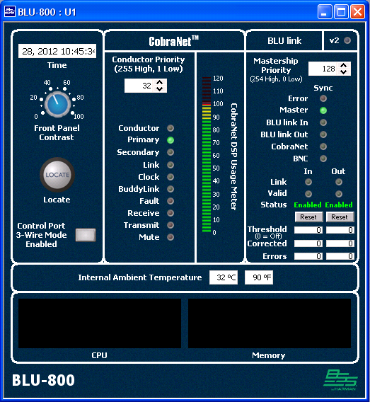
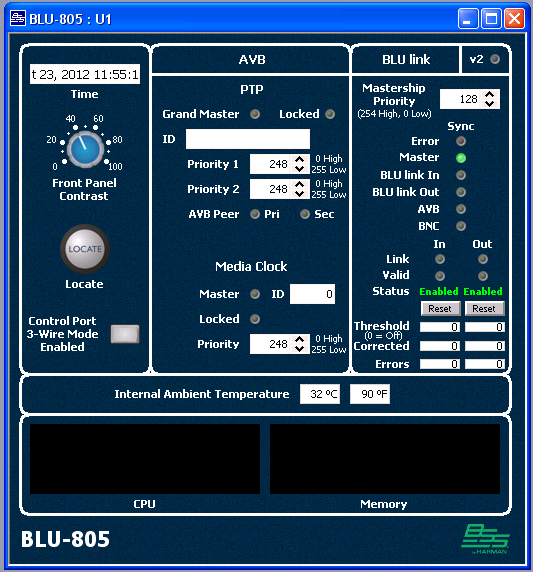
The BLU-800/BLU-320/BLU-160/BLU-120/BLU-100/BLU-101/BLU-102/BLU-805/BLU-325 control panels are like the control panels for the BLU-80/BLU-32/BLU-16 devices but with some extra features as outlined below.
BLU link V2 indicator - On if all devices connected via BLU link have BLU link version 2. BLU link version 2 has fixed latency.
Mastership Priority - 0 to 254 (254 is highest priority)
Sync LEDs - One of the following LEDs will be lit to show how this device is synchronized:-
Master - This device is clock master
BLU link In - This device is receiving clock from the BLU link 'In' connection
BLU link Out - This device is receiving clock from the BLU link 'Out' connection
CobraNet - This device is receiving clock from the CobraNet network
AVB - This device is receiving clock from the AVB network.
DANTE - This device is receiving clock from the Dante network.
BNC - This device is receiving clock from the BNC IN connection.
Error - This BLU link network is connected to multiple CobraNet/AVB networks
BNC and Error - This device is set to sync from BNC but no BNC clock is connected.
Link In - On if a valid ethernet link is present on the 'In' port
Link Out - On if a valid ethernet link is present on the 'Out' port
Valid In - On if valid BLU link audio is present on the 'In' port
Valid Out - On if valid BLU link audio is present on the 'Out' port
Corrected Counters - The corrected counters show the number of recoverable bit errors that have occurred
Error Counters - The error counters show the number of unrecoverable bit errors that have occurred
Threshold - The BLU link IN and OUT ports will be disabled when the number of errors on the error counter reaches the value set by Threshold. A setting of 0 means that the Threshold is OFF and the ports will not be disabled.
Status - Shows the status of the BLU link IN and OUT ports as Enabled or Disabled. When the port is disabled no BLU link audio will pass.
Reset - resets the error counters and sets the status of the IN and OUT ports to Enabled.
Software Configuration
The BLU link devices placed in the Main Window show the BLU link In and Out ports which allow you to wire the devices together, as shown in the diagram above. Note: It is not necessary to wire the BLU link ports together within HiQnet London Architect in order for BLU link to function.
Editing BLU link Networks
Multiple BLU link networks can exist within a London Architect design file. By default, each device belongs to BLU link 1. Every BLU link device must be part of one BLU link network. The device properties show which BLU link network the device is part of. Click on the ... icon to edit.
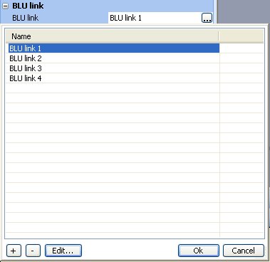
This property can be edited to add, delete, edit the name of, and assign the device to a BLU link network. The diagram above shows that four BLU link networks exist in this design file, and that the device belongs to BLU link 1 which is shown highlighted.
In the Configuration Window of a BLU-800 and a BLU-160, by default, there is one BLU link Input and one BLU link Output processing object. Initially they have no nodes on them.
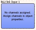
You can add and remove as many BLU link processing objects as you wish inside a BLU-800 and BLU-160. The BLU-320 by default contains 2 BLU link Inputs and 2 BLU link Outputs and the BLU-120, BLU-100, BLU-101 and BLU-102 by default contain 1 BLU link Input and 1 BLU link Output. You cannot add or delete BLU link processing objects in the BLU-320 or BLU-120.
Each BLU link processing object supports a maximum of 32 channels. To edit the channels on a BLU link processing object, select the BLU link input and click on channel assignment in the 'BLU link Channels' property of the object. This brings up the BLU link channel dialog.
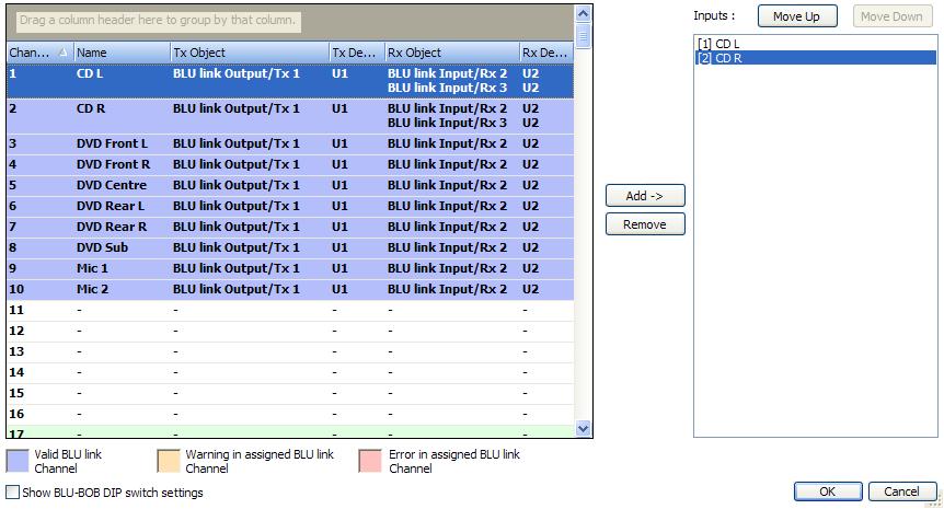
The left pane shows all the BLU link channels in the network (which the device is part of). The channels can be sorted by clicking on the column headers. Channels can also be grouped by dragging and dropping the column headers in to the space above the column headers. The columns in the list are:
Channel - The BLU link channel number. This column can include the DIP switch settings for the BLU-BOB. Enable the 'Show BLU-BOB DIP switch settings' preference at the bottom of the dialog.
Name - The signal name of the channel. This is the name of the signal which feeds the BLU link Output processing object for this channel.
Tx Object - This is the name of the BLU link Output processing object which is transmitting this channel.
Tx Device - This is the name of the BLU-XX0 device which is transmitting this channel.
Rx Object - This is the name of the BLU link Input processing object which is currently receiving this channel.
- Rx Device - This is the name of the BLU-XX0 device which is receiving this channel.
The Tx and Rx columns may contain more than one entry if multiple objects are sending/receiving the same channel. Channels shown in bold are channels which are not being transmitted by the current configuration. When configuring a BLU link Output, only channels in bold can be added to the pane on the right.
Show BLU-BOB DIP switch settings' - When enabled, displays the BLU-BOB DIP switch values (1 to 6) and the channel within that group. For example, 010001,4 is channel 140 (fourth channel in group 17).
The right pane shows the channels selected for that BLU link processing object. You can use the 'Move Up' and 'Move Down' buttons to change the order in which the channels appear on the object. To add a channel to the BLU link processing object, select one or more channels in the left pane, and press the 'Add ->' button. To remove channels from the processing object, select one or more channels in the right pane, and press the 'Remove' button.
Channels which have been partly or fully configured are in one of three states.
Valid. These channels are shown highlighted in blue. The channels have valid transmitters and receivers.
- Warning. These channels are shown highlighted in amber. There are three scenarios where a channel shows a warning:
1.No receiver. The channel is transmitting but is not being received by any device.
2.No transmitter. The channel is being received, but no device is sending the channel.
3.Possible clash. This happens when multiple configurations of different devices are transmitting on the same channel. Though it is possible to never have two configs active at the same time transmitting on the same channel, the possibility exists of two devices transmitting on the same channel. It is up to you to configure presets correctly to avoid multiple transmitters on the same channel.
Error. These channels are shown highlighted in pink. An error is shown where there is more than one device transmitting on the same BLU link channel.
You can hover your cursor over a channel to see a tool tip describing the state of the channel.
All devices on the same BLU link network must be running at the same sample rate, all at 48kHz, or all at 96kHz. If any devices are running at different sample rates, you will be warned about this when entering the channel assignment dialog. If any channels are in error (highlighted pink), or have different sample rates, then you will be prevented from going online to the devices. The BLU link channel assignments will have to be corrected.
BLU link Specification
Based on Gigabit Ethernet technology
100m over CAT5e cable.
>100m using fibre converters.
256 Channels at 48KHz (BLU-100, BLU-101 and BLU-102 are restricted to 48 channels at 48kHz)
128 Channels at 96KHz (BLU-100, BLU-101 and BLU-102 do not operate at 96kHz)
Bus-like architecture. Audio transmitted on a channel is available at all other devices on the network automatically.
Wired in a loop for redundancy
- Recovers from a single cable break