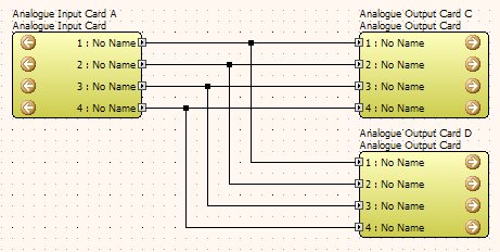
Virtual wires are used to connect the objects on the design layout and, route the signals between the connection points of internal processing objects and/or input and output ports. These wires are for design clarity and have no relationship to actual signal routing on the design layout pages (i.e. Main and in Zones) the devices must be cabled properly in the real world installation for proper operation. This includes the correct use of line level audio cabling, multicores and cat5 Ethernet cabling where appropriate.
However, when in the Configuration windows for a device, the wiring to connect processing objects is critical. Incorrect connections and unwired ports will show up in the Compiler Report as errors that can be traced back for proper connection.
1. An incorrect connection (e.g. an input to input between processing objects or trying to connect an audio output to a network port) is indicated by the wire turning red.
2. The processing objects supplied are set up for the default grid, which is 10x10 pixels. It is strongly suggested that you leave the grid on this setting, and leave the 'snap to grid' option in the toolbar enabled.
3. By default, you are permitted to create vertical, horizontal and diagonal line segments. However, you can tighten this restriction by selecting No Diagonals from the View menu (or toolbar) in order to create tidier and more presentable layouts.
4. If you are in the middle of dragging a wire and you realise that you are doing the wrong thing, pressing the ESC key will abort the drag operation. Also sometimes it seems difficult to release a wire that you may have inadvertently picked up; in this case right clicking in the design space should drop your connection to it.
5. Hovering the cursor over a wire will show the presence of audio or ‘no signal’ – the system needs to be online with an audio feed for anything to show here, thus it is a good indicator of signal flow.
To wire up multiple similar connections between devices, processing objects, input/output blocks or network bundles; select the required number of consecutive nodes (now shown in red), click on any one of the nodes and drag the wiring to the required connections.
NB: Where the connections are direct, i.e. 8 outputs to 8 inputs, the connections will be easily made. When there are differing number of connections available HiQnet London Architect will wire all those that are possible from the top down, i.e. the top connection is the anchor that all others follow. Where there are other objects in vertical alignment with the desired destination and, if these have valid connections, HiQnet London Architect will connect sequentially to as many nodes as available, i.e. across a CobraNet bundle and an analogue audio output block. The exact alignment of these objects is not absolutely vital but using the object alignment options in the Edit menu, or toolbar, will help to make sure that the connections are made properly - see layout options.
Multiple dragged wires can be made to turn 90 degrees by holding the left or right arrow key (dependent on which direction is required). The corner will be indicated and the correct angle to keep the wires evenly spaced will be shown and applied when connected to another device.
There are several methods available to wire from a single output node to multiple input nodes.
1. The most basic method is to click on the output node and wire directly to the input node. Next click on the output node again and wire to the next input node. Repeat for all nodes.
2. Add a wire from the output to the first input node. Next double click the wire to create a Y-split, and wire that to the next output node. Repeat for all nodes.
3. Multiple select all the output nodes. Click the top node to start a mutliple wire. As you move the cursor over to the input node, press the 'C' key. Keep the 'C' key pressed until you have clicked on the output node.
It is possible to combine #2 above with multi-wiring. You can select a group of input nodes, and multi-wire back to existing wires in order to create multiple Y-splits in one go. Use the left and right arrow keys (or Z and X) to stagger the multiple wires. This makes it very quick to create configurations such as the one shown below.
