The Truth Table sets its outputs according to rules associated with its input states. The input is in binary format. The truth table can be manually edited to define the state of the outputs for each input state. Alternatively a *.CSV file can be imported.
The lights on the logic object design block indicate the current state of the inputs and outputs. These are operational in simulation and when online to the device.
Edit Truth Table

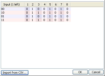
The Truth Table above is set as 2 inputs and 8 outputs. With both inputs low, outputs 2, 5 and 7 will be high, with input 1 high and input 2 low, outputs 1, 2, 4 and 7 will be high, and so on.
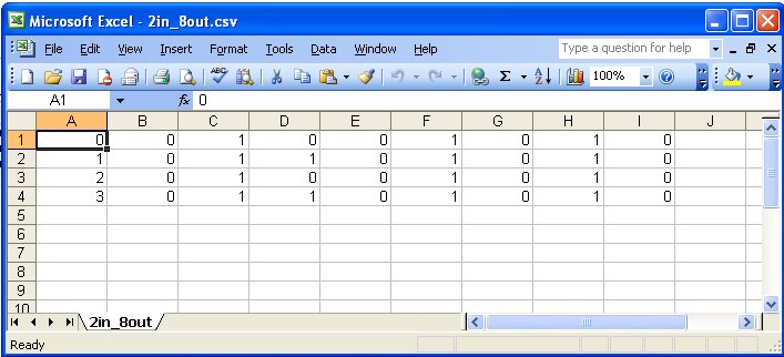
As an alternative to manually entering the states for the truth table, a *.CSV file could be imported instead by clicking on the button. The example shown below will produce the above truth table when imported. Note that the inputs states are represented in decimal.

Properties

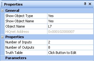
Number of Inputs
This sets the number of inputs, selectable from 2 to 12.
Number of Outputs
This sets the number of outputs, selectable from 1 to 32.
Truth Table
Click to edit the relationship between inputs and outputs.