A logic NAND gate takes two or more logic-level inputs and produces a single logic-level output. The NAND gate behaves according to the truth table below. The output of the NAND gate will be LOW (0) when both inputs are HIGH (1). Under all other conditions the output will be HIGH (1)
The lights on the logic object design block indicate the current state of the inputs and output. These are operational in simulation and when online to the device.
NAND Truth Table
A |
B |
O/P |
0 |
0 |
1 |
0 |
1 |
1 |
1 |
0 |
1 |
1 |
1 |
0 |
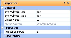
Properties

Number of Inputs
Sets the number of inputs. This is selectable from 2 to 32.