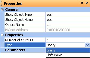
The outputs of the counter / shifter change in response to a rising edge on the INPUT pin.
The outputs can be reset by taking the RESET (R) pin high. For binary 'Type' RESET means all output pins to 0 (low) and for shift down 'Type' RESET means pin 1 to 1 (high) and all other output pins to 0. The outputs will remain in this state until the RESET pin goes high again and the INPUT pin goes high again to start the count / shift.
Taking the DIRECTION (D) pin high will cause the outputs to count or shift down rather than up.
The lights on the logic object design block indicate the current state of the inputs and output. These are operational in simulation and when online to the device.
