CobraNet bundles are capable of sending audio to up to four destinations each, bandwidth-dependent.
Multi-unicast is to be considered an advanced user feature and changing the max receivers property from the default of 1 is to be used with caution. The limits on how many bundles can be transmitter from a node are dependent on bandwidth available on the network and DSP usage on the CM1 module. Every multi-unicast configuration should be tested using real hardware before being deployed.
Configuring the multi-unicast feature
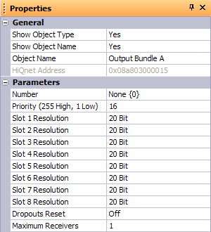
A setting in the properties grid of HiQnet London Architect, allows the maximum receivers for a given transmit bundle to be set to between 1 and 4.
To change this, open the configuration view of a BLU-80 or BLU-32 in the design. Click on a transmit bundle and click the properties tab to show the property sheet for the CobraNet transmit bundle.

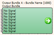
The default setting for a unicast bundle Maximum Receivers is 1, giving normal unicast bundle behaviour of one transmitter to one receiver. The transmit and receive bundle pair are coloured green under these circumstances.

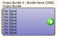
Changing this setting to 2, 3 or 4 will grant permission for additional receive bundles to receive audio. When more than 1 receiving bundle is configured with the same bundle number, the transmit bundle and associated receive bundles change colour from green to purple.

Monitoring and fault detection
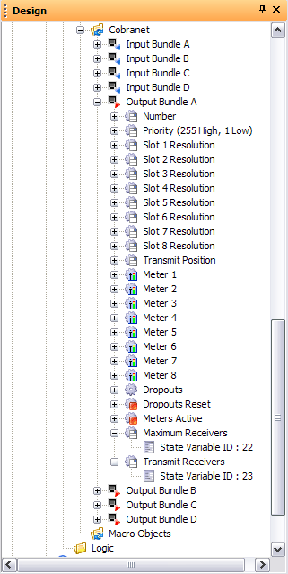
A state variable is provided which indicates the number of receivers that have been configured to receive a bundle. Please note, this does not indicate how many receivers are actually receiving the bundle, but how many have requested it. The Maximum Receivers setting presides. To use this state variable, drag it from the design tree to a control panel, and when online it will reflect the number of receivers requesting this bundle.

Reset-able dropout counters are provided on the bundle control panels. To ensure uninterrupted audio, verify that these remain at zero under all operating conditions of your network.

Capabilities
The figures quoted below are maximum bundle and channel counts found empirically, however, we strongly recommend making full use of the dropout counters on bundle control panels and the error lights on the default panel to qualify your design.
Sample rate |
Latency |
Bit depth |
number of transmit bundles |
channels per bundle |
48k |
5.333 |
16 bit |
13 |
8 channels |
|
|
20 bit |
11 |
8 channels |
|
|
24 bit |
10 |
7 channels |
|
2.666 |
16 bit |
12 |
8 channels |
|
|
20 bit |
10 |
8 channels |
|
|
24 bit |
8 |
7 channels |
|
1.333 |
16 bit |
8 |
8 channels |
|
|
20 bit |
8 |
8 channels |
|
|
24 bit |
6 |
7 channels |
96k |
5.333 |
16 bit |
14 |
4 channels |
|
|
20 bit |
11 |
4 channels |
|
|
24 bit |
12 |
3 channels |
|
2.666 |
16 bit |
12 |
4 channels |
|
|
20 bit |
10 |
4 channels |
|
|
24 bit |
8 |
3 channels + 1x20 bit |
|
|
24 bit |
11 |
3 channels |
|
1.333 |
16 bit |
8 |
4 channels |
|
|
20 bit |
7 |
4 channels |
|
|
24 bit |
6 |
3 channels + 1x20 bit |
|
|
24 bit |
7 |
3 channels |