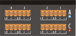

The Digital Input Cards and Digital Output Cards each have two connectors which are used as follows: -
Digital Input Cards (Card position "A" in rear panel diagram)
Connector 1 (Connector on right hand side in rear panel diagram)
Stereo Audio, Channels 1&2 - AES/EBU
Stereo Audio, Channels 3&4 - AES/EBU
Connector 2 (Connector on left hand side in rear panel diagram)
Stereo Audio, Channels 1&2 - S/PDIF
Stereo Audio, Channels 3&4 - S/PDIF
Digital Input Card Connections
|
Connector |
[S/PDIF Combicon] |
[AES/EBU Combicon] |
||
|
Signal pair |
3&4 |
1&2 |
3&4 |
1&2 |
|
Pin |
[S + -] |
[S + -] |
[S + -] |
[S + -] |
|
AES/EBU |
Positive: to + |
S/PDIF |
Signal : to + Signal Ground: to - Shield* : to S |
* Short "S" to "-" for unshielded cable
Digital Output Cards (Card position"“C" in rear panel diagram)
Connector 1 (Connector on right hand side in rear panel diagram)
Stereo Audio, Channels 1&2 - AES/EBU / S/PDIF
Stereo Audio, Channels 3&4 - AES/EBU / S/PDIF
Connector 2* (Connector on left hand side in rear panel diagram)
Clock Input - High Impedance
Clock Input - 75R Terminated
active clock selected within HiQnet London Architect
Digital Output Card Connections
|
Connector |
[Clock Input] |
[Audio Output] |
||
|
Signal pair |
3&4 |
1&2 |
3&4 |
1&2 |
|
Pin |
[S + -] |
[S + -] |
[S + -] |
[S + -] |
|
Clock Input |
Positive: to + |
AES/EBU |
Positive : to + Negative : to - Shield : to S |
|
|
S/PDIF |
Signal : to + Signal Ground: to - Shield* : to S |
|
* Short "S" to "-" for unshielded cable
Digital Card Configuration
The digital cards can be configured, within HiQnet London Architect, in the following ways: -
2 Stereo AES/EBU signals
1 Stereo AES/EBU signal / 1 Stereo S/PDIF signal
2 Stereo S/PDIF signals