Digital Cards
The Soundweb London Digital Input Cards and Digital Output Cards are designed to populate any of the four card slots on Soundweb London devices. These digital cards enable Soundweb London devices to send and receive AES/EBU and S/PDIF audio signals.
Basic Functionality

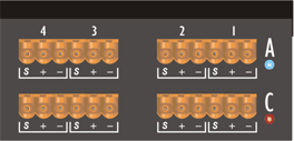
The Digital Input Cards and Digital Output Cards each have two connectors which are used as follows: -
Digital Input Cards (Card position "A" in rear panel diagram)
Connector 1 (Connector on right hand side in rear panel diagram)
Stereo Audio, Channels 1&2 - AES/EBU
Stereo Audio, Channels 3&4 - AES/EBU
Connector 2 (Connector on left hand side in rear panel diagram)
Stereo Audio, Channels 1&2 - S/PDIF
Stereo Audio, Channels 3&4 - S/PDIF
Connector |
[S/PDIF Combicon] |
[AES/EBU Combicon] |
||
Signal pair |
3&4 |
1&2 |
3&4 |
1&2 |
Pin |
[S + -] |
[S + -] |
[S + -] |
[S + -] |
AES/EBU |
Positive:
to + |
S/PDIF |
Signal : to + Signal Ground: to - Shield* : to S |
* Short "S" to "-" for unshielded cable
Digital Output Cards (Card position"C" in rear panel diagram)
Connector 1 (Connector on right hand side in rear panel diagram)
Stereo Audio, Channels 1&2 - AES/EBU / S/PDIF
Stereo Audio, Channels 3&4 - AES/EBU / S/PDIF
Connector 2 (Connector on left hand side in rear panel diagram)
Clock Input - High Impedance
Clock Input - 75R Terminated
active clock selected within HiQnet London Architect
Digital Output Card Connections
Connector |
[Clock Input] |
[Audio Output] |
||
Signal pair |
3&4 |
1&2 |
3&4 |
1&2 |
Pin |
[S + -] |
[S + -] |
[S + -] |
[S + -] |
Clock Input |
Positive:
to + |
AES/EBU |
Positive : to + Negative : to - Shield : to S |
|
S/PDIF |
Signal : to + Signal Ground: to - Shield* : to S |
|
* Short "S" to "-" for unshielded cable
Digital Card Configuration
The digital cards can be configured, within HiQnet London Architect, in the following ways: -
2 Stereo AES/EBU signals
1 Stereo AES/EBU signal / 1 Stereo S/PDIF signal
2 Stereo S/PDIF signals
Digital Cards - SyncBus
SyncBus is used to sync the Digital Output Card to another digital card.

All digital cards are connected through a parallel bus.
Each digital card has 2 SyncBus connectors so that all cards can be daisy chained together.
SyncBus is used automatically when a digital output card is synced to another digital card and the clock is sent from one card to the other.
Digital Cards - Front Panel Information on Soundweb London Devices

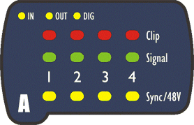
In, Out, Dig LEDs
These indicate which card is contained within the card slotDigital Input Card - 'IN' and 'DIG' illuminated
Digital Output Card - 'OUT' and 'DIG' illuminated
Sync/48V LED - illuminates to indicate that signals are synced
Signal LED - indicates signal present (illuminates at -40dBFS)
Clip LED - indicates high signal at input stage
Note: The Clip LED may illuminate frequently when using digital inputs. This is no cause for concern as digital playback media is often normalized to Full Scale, resulting in a highly optimised but implicitly safe signal.
Digital Input Card Configuration

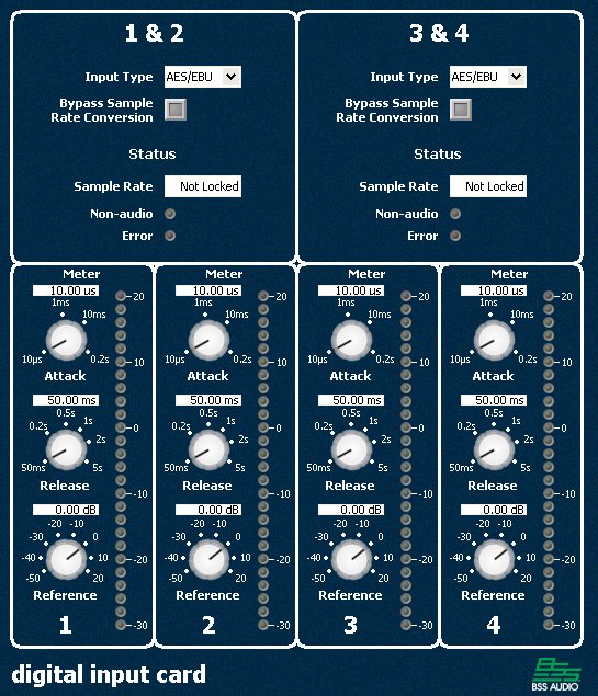
The Digital Input Card Default Control Panel allows users to configure, control and monitor a Digital Input Card.
Input Type
Input Type allows an AES/EBU or S/PDIF digital input to be selected per stereo signal.
Bypass Sample Rate Conversion
The Bypass Sample Rate Conversion button allows users to bypass the sample rate conversion per stereo signal in order to improve audio quality for matched sample rates.
Note: For trouble-free operation of Bypass Sample Rate Conversion, the external clock must be the same sample rate as the device; either 48 kHz or 96 kHz and ultimately locked to the same clock source. If the clocks are not locked drift may occur, resulting in audible clicks.
Sample Rate
Sample Rate shows the current sample rate per stereo signal.
Possible values are: -
32 kHz
44.1 kHz
48 kHz – this will also be displayed when the sample rate is at the pull-down frequency of 47.952kHz
88.2 kHz
96 kHz - this will also be displayed when the sample rate is at the pull-down frequency of 95.904kHz
Not Locked -no signal present
- Out of Range - signal is present and may be correctly received but lies outside the legal range for locking outputs
Non-audio LED
The Non-audio LED illuminates when the input is locked but receiving invalid audio. When the Non-Audio LED is illuminated the audio is muted.
Error LED
The Error LED illuminates when there is a problem with the incoming digital stream. Audio may be present but the cause of the error should be investigated.
Input Meter
The Input Meter gives clear input channel metering and offers the following ballistics properties: -
Attack - attack rate (or speed) of meter
Release - release rate (or speed) of meter
- Reference - 0dB reference point of meter
Digital Output Card Configuration
The Digital Output Card Default Control Panel allows users to configure, control and monitor a Digital Output Card.
Clock Source
Clock Source allows the digital outputs per Digital Output Card to be synchronised to the following variety of clock sources: -
Internal 44.1kHz
Internal 48kHz
External 44.1kHz/48kHz 75? Terminated
External 44.1kHz/48kHz High Impedance
Digital Card A, Channels 1 and 2
Digital Card B, Channels 1 and 2
Digital Card C, Channels 1 and 2
- Digital Card D, Channels 1 and 2
- Internal - The main board of the Soundweb London device clocks at 48 kHz or 96 kHz. The internal clock is used for the DSPs and any analogue cards fitted. Internal clocks are derived from these frequencies to provide 44.1 kHz or 48 kHz sources. A 1x or 2x multiple of the internal clock can be output. So to obtain, for example, a 96 kHz output, a user would select Internal 48 kHz (2 x 48 kHz = 96 kHz).
Note: Since the clock source is specified per digital card, it is not possible to output 44.1 kHz on one output pair and 48 kHz on the other. However, this can be achieved using more than one Digital Output Card.
- External - The Digital Output Card will lock to the rate of the external clock source providing it is 44.1 kHz or 48 kHz. There are two external inputs, one is 75 ohm terminated and the other is high impedance.
Note: The external clock source frequency is not measured by the digital output card so is always labelled 44.1 kHz / 48 kHz. The user is responsible for ensuring that the external clock frequency is correct.
The output clock frequency of a digital card is a 1x or 2x multiple of the input clock frequency. To output an 88.2 kHz audio signal the external source clock frequency must be 44.1 kHz.
Note: If, for example, the external clock frequency drifts up to 48 kHz, the output would drift to 96 kHz, even though the indicated Output Sample Rate is set to 88.2 kHz.
If an external clock frequency is selected but no clock is present, the Status will indicate 'Warning: not locked'.
Digital Card
Sync to another digital card requires that the SyncBus is fitted. Digital Output Cards can be synced to any other digital card, input (channels 1&2) or output. There are a number of invalid conditions which are detected and the status displayed appropriately. These errors are described under the Status Indicator heading in the Digital Output Card section.
When synchronising the BLU link network to an external clock at pull-down sample rate of 47.952kHz or 95.904kHz via the BNC connector on the BLU-800/BLU-805/BLU-806 or BLU-320/BLU-325/BLU-326, the main board of the Soundweb London device(s) will clock at that frequency. This means that when the digital card syncs to internal 48kHz it will in fact be running at 47.952kHz and similarly when it syncs to internal 96kHz it will be running at 95.904kHz.
Note: In the case that an error is displayed, the output clock will be suppressed resulting in no audio being output from that channel pair.
Source Sample Rate
Source sample rate shows the current Source Sample Rate per Digital Output Card. Possible values are: -
32 kHz
44.1 kHz
48 kHz
88.2 kHz
96 kHz
44.1 kHz / 48 kHz
- Not Locked
If the clock is locked, the Source Sample Rate will show the following: -
Synced to an internal clock - either 44.1 kHz or 48 kHz (matching the selected clock source)
Synced to an external clock - 44.1 kHz / 48 kHz (indicating that only those two frequencies are valid)
Synced to an input card - 32 kHz to 96 kHz (matching the input sample rate of channels 1&2)
Synced to an output card - 44.1 kHz to 96 kHz (matching the output sample rate of channels 1&2)
The Source Sample Rate will show Not
Locked in the following conditions: -
Synced to an external clock and no clock present
Synced to a digital input card which is itself not locked
- Synced to a digital output card which is itself not locked for any reason
Output Type
Output Type allows AES/EBU or S/PDIF digital outputs to be selected per stereo signal.
Output Sample Rate
Output Sample Rate allows the output sample rate to be selected per stereo signal.
Bypass Sample Rate Conversion
Bypass Sample Rate Conversion allows the signal to bypass the sample rate conversion per stereo signal in order to improve audio quality for matched sample rates.
Note: For trouble-free operation of Bypass Sample Rate Conversion, the external clock must be the same sample rate as the device; either 48 kHz or 96 kHz and ultimately locked to the same clock source. If the clocks are not locked drift may occur, resulting in audible clicks.
Status Indicator
The Status Indicator shows one of the following conditions: -
Locked
Warning: Not Locked
Error: Attempted sync to self (1)
Error: Attempted sync to analogue card (2)
Error: Attempted sync to empty slot (3)
Error: Incompatible source/sample rate (4)
- Error: Attempted sync loop (5)
Error Conditions
- (1) This nonsensical setting is detected
- (2) Analogue cards do not provide a clock signal so an attempt to sync to an analogue card will not work.
- (3) Only other digital cards can provide a clock source.
- (4) Shown when the requested output sample rate is not a multiple of the source sample rate. When this is displayed the output signal is also suppressed. For example, if the clock source is set to Internal 48 kHz and the Output Sample Rate set to 44.1 kHz, this error will be displayed. If a digital output card is locked to a digital input card that is receiving a 32 kHz signal, the incompatible message will display whatever output sample rate is selected. If a digital output card is locked to a digital input card that is not locked, or out of range, the incompatible message will display.
Note: If the card is locked to an external clock, indicated as 44.1 kHz / 48 kHz the card can not detect if the source and output are compatible. So if the user connects a 44.1 kHz external clock and selects a 48 kHz output, the actual output will be 44.1 kHz, and no incompatible status message will be displayed.
- (5) If, for example, digital card A is synced to digital card B which is synced to digital card A there is a sync loop. Up to 4 cards can be synced in a circular fashion. All cards involved will display the sync loop status message. A card that is synced to a digital output card that is synced to self will also display the sync loop status message.
Indicator Colouring
Green - Correct functionality
Orange - Warning condition, cause should be investigated
- Red - Error condition, output signal suppressed (user intervention required)
Output Meter
The Output Meter gives clear output channel metering and offers the following ballistics properties: -
Attack - attack rate (or speed) of meter
Release - release rate (or speed) of meter
- Reference - 0dB reference point of meter