Automixer Gain Sharing

In addition to the features of a conventional mixer 'Automixers' allow 'hands-free' multi-microphone mixing without the need for 'manual gain riding' to keep background noise and feedback under control.
These objects use an Adaptive Threshold Gain Sharing technique to control the attenuation in each input channel. Note that due to this automation, automatic mixers can use many DSP resources.
All inputs share the available gain; i.e. an 'open' microphone will attract the most gain. If more than one microphone is in use, the gain in the active channels is shared to give the same overall system gain. When all inputs are idle, the shared gain keeps all channels slightly active to avoid 'pumping' of the background noise. Downward expansion is however available for further reducing the background noise contribution from idle microphones. Options are provided to allow the mixer to be expanded not only within a given device, but also across the network. Aux. buses can be created and direct channel outputs may be made available for final mixing elsewhere, or for adding equalisation or other processing.
Inputs and Outputs
The number of inputs can be set from 2 to 48.
The output is either mono or stereo.
There is optionally one output for each aux. bus.
There is optionally one output for each group bus.
The direct out property produces an output per channel.
The master option adds a further Mix Input, Chain Input and Threshold Output.
The slave option adds a further Mix Input, Chain Input, Threshold Input and Chain Output.
Properties
Number of Channels:
The number of input channels can be selected between 2 and 48.
Stereo:
Set to "Yes" the automixer will have a stereo pair of outputs, L and R. In Master or Slave mode there will also be a Left and Right Mix Input
Number of Groups:
Up to 4 group output buses can be selected.
Number of Auxes:
Up to 4 aux. output buses can be selected.
Pan Law:
The law of the pan controls may be set to either -3.0dB, -4.5dB or -6.0dB. These figures relate to the attenuation applied to each channel at the central pan position.
Master/Slave Status:
For expanding the mixer, either for making a larger mixer within a device, or for splitting a mixer across more than one device. The control signals are shared using two special versions of the automixer - Master and Slave.
Voice Band filters:
Filtering may be included so that the automixing action favours frequencies in the human vocal range. This helps the mixer to distinguish between speech and noise, giving a voice signal a better chance of 'winning' against a noise signal on another channel.
Direct Outs:
In addition to a single mixed output, the individual automixed channels may be output for further processing or mixing elsewhere. These individual outputs are taken from before the mix but after any processing such as gain and so on are applied. Set to Yes if Direct outputs are required. .
Control Panel

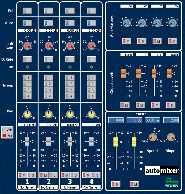
Fader for each input. This controls the level of
the channel's input before the automix logic is applied.
Pan control control (stereo objects only)
Mute button for each input.
Polarity button for each input (for signal inversion)
Gain control for each output
Solo control for each input channel for quick identification of signals and level setting: Allows only 'soloed' channels to be heard. NOTE: This feature is disabled in any 'master' or 'slave' automixer.
! This is a 'solo-in-place' which impacts the main output.
Override button for each input: Forces this channel to be heard above all the others. Useful for a chairperson to interrupt a conference speaker for example. NOTE: Use of this feature modifies the behavior of the 'On Indicator.'
Auto/Manual button assigns each channel to operate as either a conventional mixer channel (Manual) or an automated channel (Auto). It should be noted that when a channel is set to manual it will still contribute to the overall gain attenuation for the channels which are set to Auto.
Off Gain determines what maximum attenuation will be applied by the downward expander to an idle channel. The Off Gain provides some downward expansion per input, which allows the relative difference between 'winning' inputs and 'losing' inputs to be accentuated. This is useful for suppressing low level 'idle' inputs (i.e. background noise), giving a larger offset between the louder winning signal (which we want to hear) and suppressing low level signals (which we don't want to hear). When this control is set to 0dB, no downward expansion is applied. The setting of this control has some effect on the point at which the On indicators illuminate.
Gain control for the Main output(s)
Master Mute button for the Main output(s)
Slope control determines how aggressive the gain sharing is. Low slope settings cause the object to behave just like a conventional mixer. High slope settings cause the inputs to attenuate more deeply for 'closed' microphones. The fully clockwise 2:1 setting will be appropriate for most applications, but if you find the action to be too aggressive and do not want idle microphones to be 'dimmed' as much, then back this control off slightly.
Speed control determines how quickly a channel recovers from being open. Fast (anti-clockwise) settings will be needed if different speakers are speaking in quick succession since slow settings would prevent a newly active channel from fading up quickly enough. If the setting is too fast however, the gain sharing could 'pump' the gain up and down between spoken words. A setting somewhere near the centre of the travel will be found suitable in most cases.
On Indicator for each input shows when a channel is active. The 'on' level is related to the setting of the 'off gain' control. Since the gain sharing algorithm is a linear process, there is actually no concept of absolute 'on' or 'off'. Note that only one On indicator is allowed to be 'on' at a time so that the indicators may be applied to logic outputs to identify the speaker in automated camera applications. NOTE: When any channel is placed into 'Override' mode, the on indicator for that channel will be on as long as override mode is engaged. The on indicators for non-override channels will be off.
Aux Masters level and mute control for each aux bus output (Auxes are post-fader and post processing)
Group level level and mute control for each group bus output
Signal Name shows the name of the input signal
Automixer Expansion
It is possible to combine several Automixers together so that they act as one large Automixer. This makes use of the Master/Slave Status setting in the Properties Pane and also makes use of the Threshold and Chain control signals. These control signals can be passed across devices using Cobraet, Digital Audio Bus or Digital cards, if required. Note: these control signals cannot be across devices using the analogue inputs and outputs.
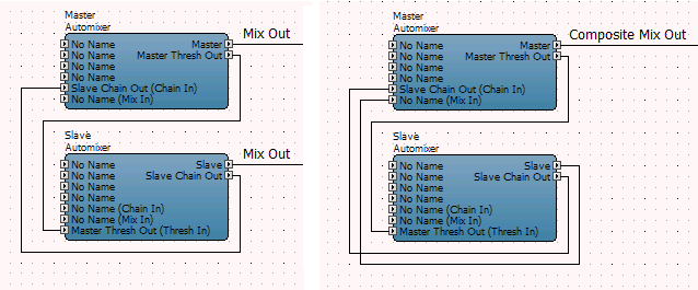
Connecting two Automixers
Connect the Threshold Out of the master to the Threshold In of the slave, and the Chain Out of the slave to the Chain In of the master. If you require the outputs of the two mixers to be combined, connect the Mix Out of the slave to the Mix In of the master, then use the Mix Out of the master.

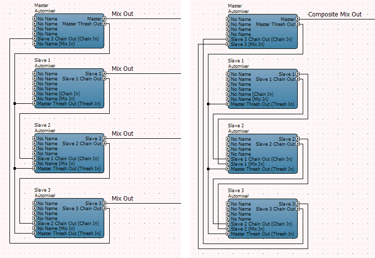
Connecting more than two Automixers
Create one master and several slaves and connect the Threshold Out on the master to all the Threshold Ins of the slaves and 'daisy chain ' the Chain Out of one slave to the Chain In of the next slave, and so on (in any order) to the Chain In of the master. If you require the outputs of all the mixers to be combined, 'daisy chain' the Mix Out of one slave to the Mix In of the next slave and so on (in any order) to the Mix In of the master, then use the Mix Out of the master.

Notes on connecting several Automixers
• The Speed and Slope controls should be set the same on all linked Automixers for correct operation.
• If you require the Aux or Group outputs of two or more Automixers you will need to combine them manually using a Summer or Mixer.
Threshold Bus and Chain control signals
Combining Automixers is made possible by distributing a Threshold bus control signal. This control signal represents the RMS sum of all the Automixers’ input signals. This control signal is required by every individual Automixer to allow all the Automixers to act as a composite Automixer.
Each slave Automixer contributes to the Threshold bus by summing its local control signal to the signal received at its Chain In input, and passing the resultant signal via its Chain Out output to the next slave Automixer’s Chain In input. These are connected in a daisy chain fashion until the last slave Automixer’s Chain Out is connected to the Chain In of the master Automixer.
The master Automixer then sums this signal with its local control signal, creating the resultant Threshold bus. This resultant Threshold bus is then sent from the master to every one of the slave Automixers, so that every Automixer receives the same resultant Threshold bus. This is achieved by connecting the Threshold Out of the master Automixer to the Threshold Input of every slave Automixer.
Notes: ! This object is capable of raising signal levels beyond the clipping point, so care should be exercised when using positive gain values.